
Unit I Basic Electrical Quantities & DC Circuits: Ohm’s Law, KCL, KVL, Mesh, Nodal & Thevenin Theorem
A complete and detailed guide to Unit I – Basic Electrical Quantities and DC Circuits covering electric charge, current, voltage, EMF, resistance, Ohm’s Law, series and parallel resistors, voltage and current dividers, DC power and energy, KCL, KVL, mesh analysis, nodal analysis, and Thevenin’s Theorem with simple examples. Study Unit I Basic Electrical Quantities and DC Circuits with detailed notes on Ohm’s Law, KCL, KVL, mesh, nodal analysis and Thevenin’s Theorem.
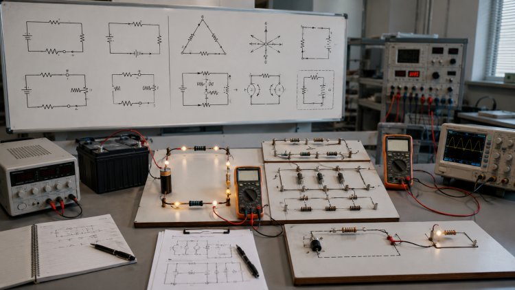
Unit I – Basic Electrical Quantities
and DC Circuits
Electrical engineering begins with a clear understanding of a few fundamental electrical
quantities and the relationships between them. Electric charge, current, voltage,
electromotive force, resistance, power, and energy form the foundation of almost
every electrical circuit. Once these quantities are understood properly, more
advanced concepts such as Ohm's Law, Kirchhoff's Laws, mesh analysis,
nodal analysis, and network theorems become much easier to understand.
DC circuits are particularly important because they provide the basic mathematical
and physical foundation for electrical engineering. A direct-current circuit generally
has a current whose reference direction remains fixed with time. Batteries, DC power
supplies, many electronic circuits, control systems, sensors, and numerous electrical
devices can be studied using DC circuit principles.
This Unit I study material provides a detailed explanation of basic electrical quantities
and DC circuit analysis. The concepts are presented in a simple and systematic
manner so that engineering students can understand both the theoretical meaning
and the mathematical application of each topic.
Table of Contents
- Electric Charge
- Electric Current
- Voltage and Potential Difference
- Electromotive Force
- Electrical Resistance
- Ohm's Law
- Resistors in Series
- Resistors in Parallel
- Voltage Divider Rule
- Current Divider Rule
- Power in a DC Circuit
- Energy in a DC Circuit
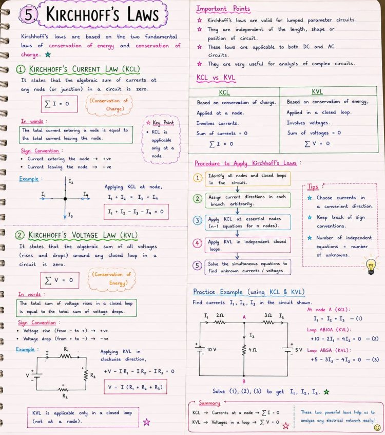
- Kirchhoff's Current Law
- Kirchhoff's Voltage Law
- Simple Mesh Analysis
- Simple Nodal Analysis
- Thevenin's Theorem
- Conclusion
- Frequently Asked Questions
Electric Charge
Electric charge is one of the fundamental properties of matter responsible for
electrical interactions. It is generally represented by the symbol Q and its SI unit
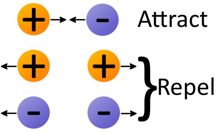
is the coulomb, represented by C. Electric charge exists in two basic forms, positive
charge and negative charge. Charges of the same type repel one another, while
opposite charges attract one another.
At the microscopic level, electrons carry negative charge and protons carry positive
charge. In metallic conductors, electrons are the primary mobile charge carriers.
When these charge carriers experience an electric field and acquire a net directed
motion, an electric current can be established through the conductor.
The magnitude of charge associated with a single electron is approximately
1.602 × 10⁻¹⁹ coulomb. Therefore, one coulomb represents a very large number
of elementary charges. Understanding charge is important because electric current
is defined in terms of the rate at which charge passes through a particular cross-section
of a conductor.
Charge can be transferred from one object to another by different physical processes.
However, in an electrical circuit, the important idea is that charge is not simply created
or destroyed at an ordinary circuit node. This concept of charge conservation forms the
physical foundation of Kirchhoff's Current Law.
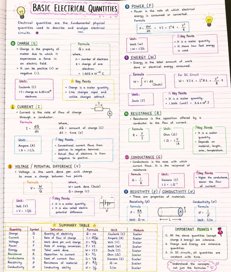
Electric Current
Electric current is the rate of flow of electric charge through a conductor or circuit element.
It is represented by the symbol I and its SI unit is the ampere, abbreviated as A.
Mathematically, current can be expressed as the amount of charge passing through a
cross-section per unit time.
I = Q / t
where I is current, Q is charge, and t is time. More generally, when the current changes
with time, instantaneous current can be expressed using the rate of change of charge
with respect to time.

In metallic conductors, electrons move in the direction opposite to the conventional current
direction. For circuit analysis, however, conventional current is normally assumed to flow
from the positive terminal toward the negative terminal through the external circuit. This
convention makes circuit calculations consistent.
In a DC circuit, the current direction is generally considered constant with time, although
its magnitude may depend on the circuit conditions. The current flowing through a resistor
is determined by the applied voltage and the resistance of that resistor.
Voltage and Potential Difference
Voltage is the electrical potential difference between two points in a circuit. It represents
the amount of electrical energy difference per unit charge between those points. Voltage
is represented by V and its SI unit is the volt.
A potential difference provides the driving condition required for current to flow through
a conducting path. If a voltage source is connected across a closed resistive circuit, the
source establishes an electric field that causes charge carriers to move through the circuit.
Voltage is always measured between two points. Unlike current, which is associated with
the flow through a particular branch, voltage describes the potential difference between
two locations in a circuit.
Voltage polarity is important during circuit analysis. A voltage can be assigned a positive
and negative reference. If a calculated voltage is negative relative to the assumed polarity,
it simply indicates that the actual polarity is opposite to the chosen reference.
Electromotive Force or EMF
Electromotive Force, commonly abbreviated as EMF, is the energy supplied by an electrical
source per unit charge. Despite its name, EMF is not actually a mechanical force.
It is measured in volts because it represents energy supplied per unit charge.
Batteries, generators, solar cells, and other sources can provide EMF to an electrical
circuit. A battery, for example, uses chemical energy to establish an electrical potential
difference and provide energy to charges moving through an external circuit.
For an ideal voltage source, the terminal voltage can be considered equal to its EMF.
In a practical source, internal resistance causes a voltage drop inside the source
when current flows. Therefore, the terminal voltage may be lower than the source's
EMF when the source supplies current to a load.
Electrical Resistance
Electrical resistance is the property of a material or circuit element that opposes the
flow of electric current. Resistance is represented by R and its SI unit is the ohm,
represented by Ω.
The resistance of a uniform conductor depends on its material, length, cross-sectional
area, and temperature. For a uniform conductor, resistance can be expressed as:
R = ρL / A
Here, ρ represents the resistivity of the material, L represents the length of the
conductor, and A represents its cross-sectional area.
This relationship shows that, for a given material and temperature, increasing the
length of a conductor increases its resistance, while increasing its cross-sectional
area decreases its resistance.
Copper and aluminium are widely used in electrical wiring because they have relatively
low resistivity and therefore allow current to flow efficiently. Resistors, on the other
hand, are manufactured using materials and structures designed to provide controlled
resistance.
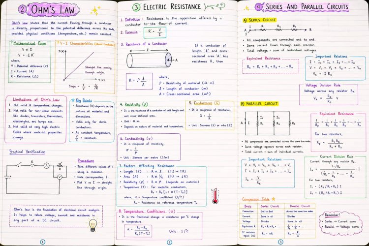
Ohm's Law
Ohm's Law is one of the most fundamental laws used in DC circuit analysis. It describes
the relationship between voltage, current, and resistance for an ohmic conductor under
constant physical conditions.

V = IR
In this equation, V represents voltage, I represents current, and R represents resistance.
By rearranging the equation, current and resistance can also be calculated.
I = V / R
R = V / I
For example, if a 20 V voltage is applied across a 10 Ω resistor, the current through
the resistor is:
I = 20 / 10 = 2 A
Ohm's Law is extremely useful for solving simple electrical circuits. However, it is
important to understand that not every electrical device behaves as an ideal ohmic
resistor. Devices such as diodes and transistors can have nonlinear voltage-current
characteristics, so Ohm's Law must be applied appropriately.
Resistors in Series
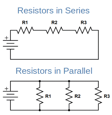
Two or more resistors are said to be connected in series when they are arranged so
that the same current must pass through each resistor. In a simple series circuit, there
is only one available path for current.
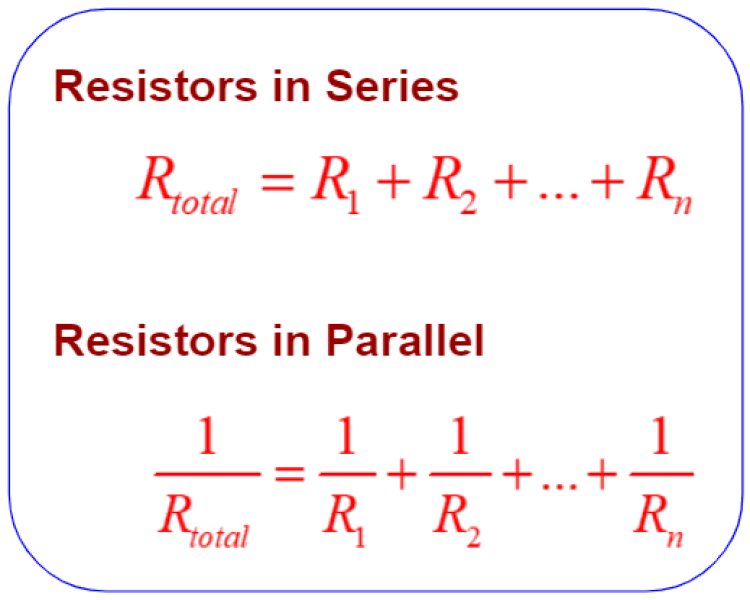
The equivalent resistance of resistors connected in series is equal to the sum of their
individual resistances.
Req = R1 + R2 + R3 + ...
For example, if 2 Ω, 3 Ω, and 5 Ω resistors are connected in series, the equivalent
resistance is:
Req = 2 + 3 + 5 = 10 Ω
The current through each series resistor is the same, but the voltage drop across
each resistor can be different. The resistor having the larger resistance experiences
a larger voltage drop when the same current flows through all the resistors.
Series resistance is frequently used in voltage divider circuits, current limiting
applications, and many practical electrical networks.
Resistors in Parallel
Resistors are connected in parallel when their corresponding terminals are connected
to the same two nodes. A major characteristic of a parallel circuit is that every parallel
branch has the same voltage across it.
For two resistors connected in parallel, the equivalent resistance is:
Req = (R1R2) / (R1 + R2)
For three or more resistors, the reciprocal relationship can be used:
1/Req = 1/R1 + 1/R2 + 1/R3 + ...
The equivalent resistance of a parallel network is normally lower than the smallest
individual branch resistance. This occurs because parallel branches provide multiple
paths for current.
For example, if two 6 Ω resistors are connected in parallel, their equivalent resistance is:
Req = (6 × 6)/(6 + 6) = 3 Ω
Voltage Divider Rule
The Voltage Divider Rule is used to determine the voltage across individual resistors
connected in series. Since the same current flows through all series resistors, the
voltage drop across each resistor is proportional to its resistance.
Consider two series resistors R1 and R2 connected across a source voltage V.
The voltage across R2 is:
V2 = V × R2 / (R1 + R2)
Similarly, the voltage across R1 is:
V1 = V × R1 / (R1 + R2)
For example, if a 12 V source is connected across a 2 Ω and 4 Ω series network,
the voltage across the 4 Ω resistor is:
V2 = 12 × 4/(2 + 4) = 8 V
The remaining 4 V appears across the 2 Ω resistor. The two voltage drops add to the
source voltage, which is consistent with Kirchhoff's Voltage Law.
Voltage dividers are widely used in electrical and electronic circuits to obtain a desired
fraction of an input voltage. In practical applications, the effect of any load connected
to the divider must also be considered.
Current Divider Rule
The Current Divider Rule is used in parallel circuits to determine how total current is
distributed among parallel branches. Since every parallel branch has the same
voltage, the branch with lower resistance carries a larger current and the branch
with higher resistance carries a smaller current.
For two parallel resistors R1 and R2 carrying a total current I, the current through R1 is:
I1 = I × R2 / (R1 + R2)
The current through R2 is:
I2 = I × R1 / (R1 + R2)
For example, suppose a total current of 6 A enters two parallel resistors of 2 Ω and
4 Ω. The current through the 2 Ω branch will be greater because that branch has
lower resistance.
Current division is particularly useful when analyzing parallel networks and circuits
containing multiple current paths.
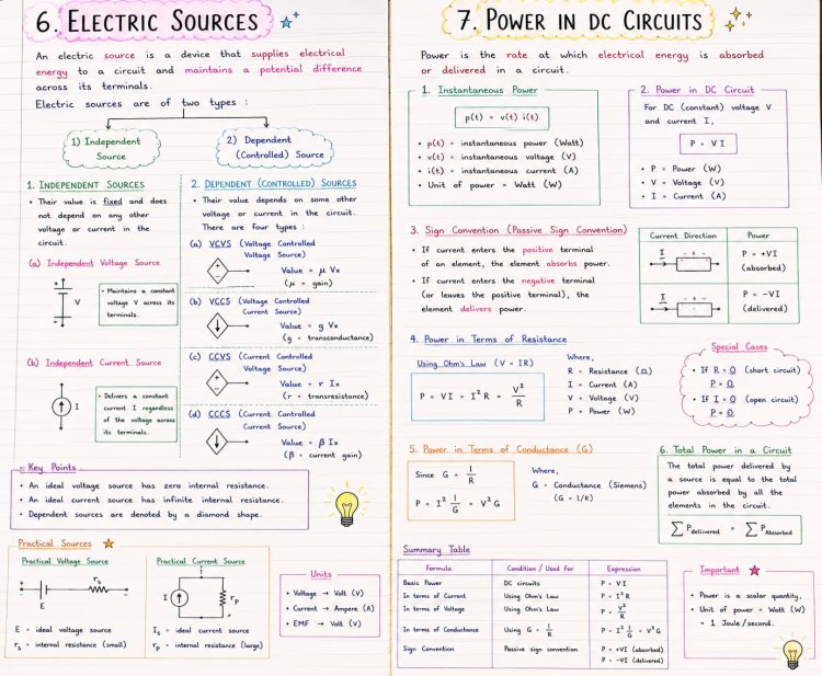
Electrical Power in a DC Circuit
Electrical power represents the rate at which electrical energy is transferred, consumed,
or delivered. It is represented by P and its SI unit is the watt.
The basic DC power relationship is:
P = VI
Using Ohm's Law, the power equation can also be written in two other useful forms:
P = I²R
P = V²/R
These three equations are mathematically equivalent when Ohm's Law applies.
The most convenient form depends on the quantities known in the problem.
For example, if a resistor carries 2 A current and has a resistance of 5 Ω, its power
consumption is:
P = I²R = 2² × 5 = 20 W
In a passive resistor, electrical power is generally converted into heat. This
phenomenon is called resistive power dissipation. It is important in electrical
design because excessive power dissipation can cause components to overheat or fail.
Electrical Energy in a DC Circuit
Electrical energy is the total amount of electrical work transferred or consumed
over a period of time. If a circuit consumes power P for a time t, the energy can be
expressed as:
E = Pt
Since DC power can be written as VI, electrical energy can also be expressed as:
E = VIt
The SI unit of energy is the joule. Electrical energy used by households is commonly
measured in kilowatt-hours, abbreviated as kWh.
One kilowatt-hour represents the energy consumed when a device operating at 1 kW
operates continuously for one hour. Understanding the difference between power and
energy is important because power represents the rate of energy consumption, while
energy represents the total amount consumed over time.
Kirchhoff's Current Law or KCL
Kirchhoff's Current Law is one of the most important laws used for electrical circuit
analysis. KCL is based on the conservation of electric charge. It states that the
algebraic sum of currents at any node or junction of an electrical circuit is zero.
ΣI = 0
Another way of stating KCL is that the total current entering a node must equal the
total current leaving that node.
Total Entering Current = Total Leaving Current
For example, if currents I1 and I2 enter a node and current I3 leaves the node, then:
I1 + I2 = I3
KCL is particularly useful for analyzing circuits containing multiple branches. It is also
the fundamental law used in nodal analysis.
When solving a circuit, current directions can initially be assumed. If the final calculated
value is negative, it simply indicates that the actual current flows opposite to the assumed direction.
Kirchhoff's Voltage Law or KVL
Kirchhoff's Voltage Law is based on the principle of conservation of energy. It states
that the algebraic sum of all voltage rises and voltage drops around any closed loop
in a circuit is zero.
ΣV = 0
For a simple circuit containing a voltage source V and two resistor voltage drops V1
and V2, the KVL equation can be written as:
V - V1 - V2 = 0
Therefore:
V = V1 + V2
KVL is extremely useful for series circuits and mesh analysis. When writing KVL
equations, a consistent sign convention should be used. A voltage rise can be
assigned one sign and a voltage drop the opposite sign.
Simple Mesh Analysis
Mesh analysis is a systematic circuit analysis method based primarily on Kirchhoff's
Voltage Law. It is especially useful for planar circuits containing several loops or meshes.
The basic idea is to assign a mesh current to each independent mesh of the circuit.
A convenient direction, commonly clockwise, is selected for all mesh currents. KVL equations are then written for each mesh.
If a resistor belongs to only one mesh, its voltage drop is determined by the resistance multiplied by the corresponding mesh current. If a resistor is common to two meshes, the current through that resistor depends on the difference between the two mesh currents, according to the selected reference directions.
Simple Mesh Analysis Example
Consider a simple closed loop containing a 12 V DC source and two series resistors of 4 Ω and 2 Ω. Since there is only one loop, a single mesh current I can be assumed.
Applying KVL around the loop gives:
12 - 4I - 2I = 0
Therefore:
12 = 6I
I = 2 A
Thus, the current flowing through both series resistors is 2 A. The voltage drop across the 4 Ω resistor is 8 V, while the voltage drop across the 2 Ω resistor is 4 V. Their sum is 12 V, which satisfies KVL.
Simple Nodal Analysis
Nodal analysis is a circuit analysis technique used to determine the voltage at different nodes in an electrical network. It is primarily based on Kirchhoff's Current Law.
The first step in nodal analysis is to select one node as the reference node. This node is normally assigned a voltage of zero and is often called the ground node. The voltages of all other important nodes are then treated as unknown variables.
KCL is applied at each non-reference node. The current through a resistor connecting two nodes can be expressed in terms of the voltage difference between the nodes divided by the resistance.
I = (V1 - V2) / R
For example, if a node with voltage V is connected to ground through a resistor R, the current flowing from that node toward ground is:
I = V/R
Simple Nodal Analysis Example
Consider a node with voltage V connected through a 2 Ω resistor to a 4 V source and through a 4 Ω resistor to ground. Applying KCL at the node gives:
(V - 4)/2 + V/4 = 0
Multiplying the equation by 4 gives:
2(V - 4) + V = 0
Therefore:
3V = 8
V = 8/3 V
Thus, the node voltage is approximately 2.67 V. This example demonstrates the fundamental idea of nodal analysis: express branch currents using node voltages and then apply KCL.
Thevenin's Theorem
Thevenin's Theorem is one of the most useful network theorems for simplifying complex linear electrical circuits. It states that any linear two-terminal network can be represented, from the perspective of its two terminals, by an equivalent voltage source connected in series with an equivalent resistance.
The equivalent voltage source is called the Thevenin voltage, represented by Vth, while the equivalent resistance is called the Thevenin resistance, represented by Rth.
Vth = Open-Circuit Voltage at the Load Terminals
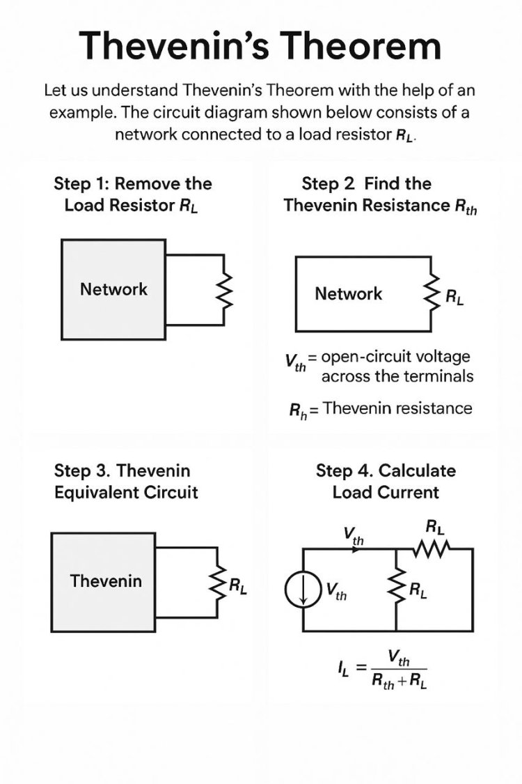
To determine the Thevenin equivalent, the load connected to the output terminals is first removed. The open-circuit voltage measured across those terminals is then determined. This voltage is Vth.
Next, the equivalent resistance looking back into the circuit from the load terminals is determined. When independent sources are present, an ideal independent voltage source is replaced by a short circuit and an ideal independent current source is replaced by an open circuit.
Rth = Equivalent Resistance Seen from Load Terminals
Simple Thevenin's Theorem Problem
Suppose a linear network has an open-circuit voltage of 12 V at its output terminals. After deactivating the independent sources, the resistance measured from those terminals is found to be 4 Ω.
Therefore, the Thevenin equivalent consists of a 12 V voltage source in series with a 4 Ω resistance.
Now suppose a 2 Ω load resistor is connected to this Thevenin equivalent circuit. The load current can be calculated directly using Ohm's Law:
IL = Vth / (Rth + RL)
Substituting the values:
IL = 12 / (4 + 2)
IL = 2 A
Therefore, the load current is 2 A. The major advantage is that the original complicated network no longer needs to be analyzed for every new load value. Once its Thevenin equivalent is known, different loads can be analyzed quickly.
Importance of Thevenin's Theorem
Thevenin's Theorem is particularly useful when a circuit has a complex internal network but only the behavior at two output terminals is important. It can significantly simplify repeated load calculations and is widely used in electrical and electronic circuit analysis.
Relationship Between the Basic DC Circuit Concepts
The concepts covered in this unit are closely connected. Electric charge is the fundamental electrical quantity, and its directed movement gives rise to electric current. Voltage represents electrical potential difference and provides the driving condition for current. EMF describes the energy supplied per unit charge by a source, while resistance opposes current flow.
Ohm's Law establishes the basic relationship between voltage, current, and resistance. Once this relationship is understood, series and parallel resistor networks can be simplified. Voltage divider and current divider rules then provide convenient methods for finding individual voltages and branch currents.
Power and energy describe how electrical energy is transferred and consumed. When circuits become more complicated, Ohm's Law alone may not be sufficient. Kirchhoff's Current Law and Kirchhoff's Voltage Law provide systematic methods for analyzing complex networks.
Mesh analysis uses KVL to determine loop currents, while nodal analysis uses KCL to determine node voltages. Thevenin's Theorem takes the simplification concept one step further by replacing an entire linear two-terminal network with an equivalent voltage source and series resistance.
Why Unit I Is Important for Electrical Engineering Students
Unit I is not merely an introductory chapter. It establishes the language and mathematical foundation used throughout electrical engineering. Students who understand voltage, current, resistance, power, energy, KCL, and KVL clearly will find later topics such as AC circuits, network theorems, electrical machines, power systems, control systems, and electronic circuits easier to study.
For examination preparation, students should understand the physical meaning of every quantity along with its symbol and SI unit. Formula memorization alone is not enough. The ability to identify the correct circuit configuration and select an appropriate analysis method is equally important.
Students should also practice simple numerical problems involving series and parallel resistors, voltage division, current division, power calculations, KCL, KVL, mesh analysis, nodal analysis, and Thevenin equivalent circuits. Repeated practice improves both calculation speed and confidence.
Conclusion
Unit I – Basic Electrical Quantities and DC Circuits provides the foundation for understanding electrical engineering. Electric charge, current, voltage, EMF, and resistance are the basic quantities from which the behavior of electrical circuits can be understood.
Ohm's Law establishes the fundamental relationship between voltage, current, and resistance. Series and parallel resistor combinations make it possible to simplify circuits, while voltage divider and current divider rules provide quick methods for determining individual circuit quantities.
Power and energy describe the rate and total amount of electrical energy transfer. Kirchhoff's Current Law is based on charge conservation, while Kirchhoff's Voltage Law is based on energy conservation. These two laws provide the foundation for systematic circuit analysis.
Mesh analysis uses KVL to determine loop currents, while nodal analysis uses KCL to determine node voltages. Finally, Thevenin's Theorem provides a powerful method for replacing a complex linear two-terminal network with a simple equivalent voltage source and series resistance.
A strong understanding of these topics will help students solve DC circuit problems more confidently and will provide a solid foundation for the advanced electrical engineering concepts studied in subsequent units.
Frequently Asked Questions
(1) What is electric charge?
Answer : Electric charge is a fundamental property of matter responsible for electrical interactions. Its SI unit is the coulomb.
(2) What is the SI unit of electric current?
Answer : The SI unit of electric current is the ampere, represented by A.
(3) What is voltage?
Answer : Voltage is the electrical potential difference between two points. Its SI unit is the volt.
(4) What is EMF?
Answer : Electromotive force is the energy supplied by an electrical source per unit charge. It is measured in volts.
(5) What is resistance?
Answer : Resistance is the property of a circuit element or material that opposes the flow of electric current. Its SI unit is the ohm.
(6) What is Ohm's Law?
Answer : Ohm's Law states that, under constant physical conditions for an ohmic conductor, voltage is proportional to current. The basic equation is V = IR.
(7) What happens to current in a series circuit?
Answer : The same current flows through all elements connected in a simple series path.
(8) What happens to voltage in a parallel circuit?
Answer :All branches connected between the same two nodes have the same voltage across them.
(9) What is KCL?
Answer : Kirchhoff's Current Law states that the algebraic sum of currents at a node is zero, or equivalently, total current entering a node equals total current leaving it.
(10) What is KVL?
Answer :Kirchhoff's Voltage Law states that the algebraic sum of all voltage rises and voltage drops around a closed loop is zero.
(11) Which Kirchhoff law is used in mesh analysis?
Answer : Mesh analysis primarily uses Kirchhoff's Voltage Law.
(12) Which Kirchhoff law is used in nodal analysis?
Answer :Nodal analysis primarily uses Kirchhoff's Current Law.
(13) What is Thevenin's Theorem?
Answer :Thevenin's Theorem states that a linear two-terminal network can be represented by an equivalent voltage source in series with an equivalent resistance.
(14) What is Thevenin voltage?
Answer :Thevenin voltage is the open-circuit voltage measured across the two terminals of the network from which the load has been removed.
(15) What is Thevenin resistance?
Answer :Thevenin resistance is the equivalent resistance seen from the load terminals after appropriately deactivating the independent sources.































.svg)