Fundamentals of Electrical Engineering unit-I: DC Circuits Notes & Analysis
Complete Unit-1 DC Circuits notes for 2nd semester Electrical Engineering. Covers R, L, C elements, Kirchhoff’s Laws, Mesh & Nodal Analysis with PDF download.

Fundamentals of Electrical Engineering
Unit – 1: DC Circuits (Second Semester)
Introduction
Electrical Engineering is one of the core branches of engineering that deals with the study, design, and application of electrical systems and components. In the second semester of most diploma and B.Tech programs, Fundamentals of Electrical Engineering (FEE) forms the foundation for advanced subjects like Electrical Machines, Power Systems, Control Systems, and Power Electronics.
Unit–1 of this subject mainly focuses on DC Circuits, which are the building blocks of electrical network analysis. Understanding DC circuits helps students develop analytical skills required for solving real-life electrical problems.
This detailed post covers the following topics:
-
Electrical Circuit Elements (R, L and C)
-
Concept of Active and Passive Elements
-
Voltage and Current Sources
-
Concept of Linearity
-
Unilateral and Bilateral Elements
-
Kirchhoff’s Laws
-
Mesh Method of Analysis
-
Nodal Method of Analysis
-
Adding PDF Notes
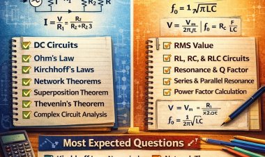
1. DC Circuits – Basic Concept
A DC circuit (Direct Current Circuit) is an electrical network powered by a DC source where the current flows in one direction only.
In DC circuits:
-
Voltage polarity remains constant.
-
Current direction does not change with time.
-
Examples: Battery-operated circuits, DC motors, LED circuits, mobile chargers (after rectification stage).
A simple DC circuit consists of:
-
Source (battery or DC supply)
-
Conductors (wires)
-
Load (resistor, lamp, motor, etc.)
The fundamental relation governing DC circuits is Ohm’s Law:
Where:
V = Voltage (Volts)
I = Current (Amperes)
R = Resistance (Ohms)
2. Electrical Circuit Elements (R, L and C)
Electrical circuits are made of three fundamental passive elements:
-
Resistor (R)
-
Inductor (L)
-
Capacitor (C)
These are called basic circuit elements.
2.1 Resistor (R)
A resistor is a device that opposes the flow of electric current.
Formula:
Unit:
Ohm (Ω)
Function:
-
Limits current
-
Divides voltage
-
Dissipates power as heat
Power Dissipation:
Types of Resistors:
-
Carbon resistor
-
Wire-wound resistor
-
Variable resistor (Potentiometer)
Properties:
-
Does not store energy
-
Purely dissipative element
-
Linear device (if temperature constant)
2.2 Inductor (L)
An inductor is a device that stores energy in the form of a magnetic field.
Formula:
Where:
L = Inductance (Henry)
Unit:
Henry (H)
Characteristics:
-
Opposes change in current
-
Stores energy in magnetic field
-
In steady DC state → behaves like short circuit
Energy Stored:
Applications:
-
Transformers
-
Chokes
-
Filters
2.3 Capacitor (C)
A capacitor stores energy in the form of an electric field.
Formula:
Where:
C = Capacitance (Farad)
Unit:
Farad (F)
Characteristics:
-
Opposes change in voltage
-
Stores energy in electric field
-
In steady DC → behaves like open circuit
Energy Stored:
Applications:
-
Filtering
-
Energy storage
-
Timing circuits
3. Active and Passive Elements
Electrical elements are classified as:
-
Active elements
-
Passive elements
3.1 Active Elements
An active element is one that can supply energy to a circuit.
Examples:
-
Battery
-
Generator
-
Current source
-
Voltage source
Characteristics:
-
Provides power
-
Maintains voltage or current
3.2 Passive Elements
A passive element cannot generate energy. It can only absorb or store energy.
Examples:
-
Resistor
-
Inductor
-
Capacitor
Key Difference:
| Active Element | Passive Element |
|---|---|
| Supplies energy | Absorbs/stores energy |
| Example: Battery | Example: Resistor |
4. Voltage and Current Sources
Sources are devices that provide energy to the circuit.
4.1 Voltage Source
A voltage source maintains a constant voltage across its terminals.
Types:
-
Ideal Voltage Source
-
Practical Voltage Source
Ideal Voltage Source:
-
Internal resistance = 0
-
Voltage remains constant regardless of current
Practical Voltage Source:
-
Has small internal resistance
-
Voltage drops under load
4.2 Current Source
A current source maintains constant current.
Types:
-
Ideal Current Source
-
Practical Current Source
Ideal Current Source:
-
Infinite internal resistance
-
Current remains constant
Practical Current Source:
-
Has high internal resistance
-
Current slightly varies
5. Concept of Linearity
A system is linear if it satisfies:
-
Superposition Principle
-
Homogeneity Principle
Superposition:
Response due to multiple sources = Sum of responses due to each source.
Example:
If input doubled → output doubles.
Linear Elements:
-
Resistor (constant R)
-
Ideal inductor
-
Ideal capacitor
Non-Linear Elements:
-
Diode
-
Transistor
-
SCR
6. Unilateral and Bilateral Elements
6.1 Bilateral Element
A bilateral element behaves the same in both directions of current.
Example:
-
Resistor
-
Inductor
-
Capacitor
6.2 Unilateral Element
A unilateral element behaves differently in opposite directions.
Example:
-
Diode
-
Transistor
7. Kirchhoff’s Laws
Kirchhoff’s laws are fundamental laws used to analyze complex circuits.
They are:
-
Kirchhoff’s Current Law (KCL)
-
Kirchhoff’s Voltage Law (KVL)
7.1 Kirchhoff’s Current Law (KCL)
Statement:
The algebraic sum of currents at a node is zero.
Incoming currents = Outgoing currents
Example:
If:
I₁ + I₂ = I₃
Then:
I₁ + I₂ - I₃ = 0
7.2 Kirchhoff’s Voltage Law (KVL)
Statement:
The algebraic sum of voltages around any closed loop is zero.
Voltage rise = Voltage drop
8. Mesh Method of Analysis
Mesh analysis is based on KVL.
Steps:
-
Identify meshes
-
Assign mesh currents
-
Apply KVL in each loop
-
Solve equations
Advantage:
-
Useful for planar circuits
-
Reduces equations
Example:
For two-loop circuit:
Loop 1:
Loop 2:
Solve simultaneous equations.
9. Nodal Method of Analysis
Nodal analysis is based on KCL.
Steps:
-
Select reference node (ground)
-
Assign node voltages
-
Apply KCL at nodes
-
Solve equations
Example:
At node:
Solve for unknown voltage.
Advantage:
-
Best for circuits with many current sources
-
Easier than mesh for large networks
10. Comparison: Mesh vs Nodal Analysis
| Mesh Analysis | Nodal Analysis |
|---|---|
| Based on KVL | Based on KCL |
| Uses loop currents | Uses node voltages |
| Suitable for planar circuits | Suitable for any circuit |
| Fewer equations if fewer loops | Fewer equations if fewer nodes |
11. Importance of DC Circuit Analysis
Understanding DC circuits helps in:
-
Designing power supplies
-
Battery systems
-
Electric vehicles
-
Control systems
-
PCB design
-
Electrical machine study
It forms the foundation of:
-
Network theory
-
Power electronics
-
Electrical machines
------------------------------------------------------------------------------------------------------
Click Here to Download Complete Syllabus of First Year
Previous Year Question Paper Of FEE(Click Here to Download)
Previous Year Question Papers Of All Subjects Related with First Year(Click Here)


.svg)